
Software drawing is one of the most used programs for 3D drawings, mainly by beginners and architects due to its ease of use, powerful features and the production of excellent electronic models. But it can be used for designing parts and objects for various purposes. In the case of the additive manufacturing this is a perfect option.
One of the great differences over other 3D modeling software is its freedom to draw, where lines can be projected in any direction and face form whenever these lines close in a plane.
But all this freedom can result in some errors that undermine the project’s printability in 3D, in some cases making a 3D project made in the software unprintable. All this is for the simple fact that the model is not solid.
But what does it mean to say that a model is not solid in SketchUp?
A solid group or component in the software means that that object has two faces on each edge, that is, it is a fully enclosed enclosure, with no holes, nothing inside, nothing left. With the examples below you can better understand this concept.
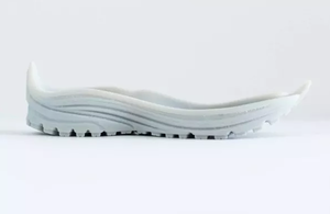
To check if a group or component is solid, just right-click on it and click on entity information, the word solid should appear in the window that opens, if not, it means that it does not appear. It is solid and some corrections will be required for it to become one and can be printed in 3D. The most common errors will be presented below to help you correct your designs for 3D printing. For this, we will use the model of the image above and cause some errors in it to exemplify.
Inverted Knives
This is one of the most common errors, but it is not very serious in most cases, such a simple part can print in 3D even with reverse faces, but in some more complex models, it can cause printing errors. So be careful about this and avoid creating models with inverted faces, leaving white faces outside and blue faces inside.
Failure of Knives or Holes or Knives Not Connected

Another flaw that occurs a lot is the lack of faces, or the faces are not fully connected, creating holes in the model, causing the part not to print correctly, there is software that can correct and close these holes, but it is better to avoid them because you know what automatic corrections look like. Often these flaws can be difficult to identify and fix, so we advise you to install the Solid Inspector plugin, which helps identify these flaws.
Internal Faces
Another error that occurs a lot, difficult to be repaired automatically with total satisfaction and that causes serious errors in the production of the part. Do not leave faces inside the object.
Loose Edges
Loose edges on the inside, outside, or on faces of a group or component, commonly used as guides, prevent it from being recognized as solid, but are even causing printing errors and are easily corrected automatically by Plugins like Solid Inspector.
Object Intersection and Faces
Do not let stools and objects intersect in this way, this can generate files with errors at print time, severe failures, and difficult to fix automatically. The geometry of a solid must not be within another solid. Use the external reversing tool so that the intersection between them is removed and becomes a single solid.